Selection Tips for Choosing the Right LB System for YouDesign Concepts, Features and PerformanceContents 4. Conclusion.
1. AbstractAn analysis of the main design concepts used in the manufacture of today Langmuir-Blodgett (LB) film deposition systems is presented . A critical comparison is made between the 4th generation of LB systems (500 series) designed by Advanced Technologies Ltd. (AT) and the last modifications from its major competitors: Nima Technologies Ltd. (U.K.), KSV Instruments Ltd. (Finland), and Nippon Laser and Electronics (NLE) Lab. (Japan). Analysed are all major components: trough and barrier, temperature control, surface pressure meter, barrier moving mechanism, film deposition system. Our aim is to help our customers with competent advice on choosing the correct instrument for their needs. We wish to draw attention on specific equipment problems and trade-offs, which are not usually discussed in equipment leaflets, and which contribute to the precision of operation and ease of work. 500 series from ATL is the best specified LB film deposition system currently on the market. It is designed as a top performing equipment for advanced research needs. Several new trends are incorporated in the design: modularity – one system can work with different troughs for the different experiments, or can be upgraded; open and compact design for easy integration with other research equipment like microscopes, spectrophotometers, etc.; built-in features for complete control of experimental conditions and work with different type of compounds in different experiments. This is the only commercially available system with built-in temperature control (option). With lower cost and improved precision compared to external thermostat with cooling features, the built-in temperature control allows complex experiments like isobars and isochores or thermal cycling at given position of the phase diagram for film quality improvement. The temperature range in the 500 series is considerably improved, compared to 400 series and now it is from 5 to 40 OC, software limited; the accuracy of control is ұ 0.05 OC within 1 hour from experiment start; the desired temperature is usually reached within 10 minutes. Most importantly this is the true temperature in the water subphase measured in the dipping well and not the temperature anywhere else where we have shown that the errors can be as high as 10 OC. We were able to produce these highest quality very reliable
systems and at the same time maintain competitive prices on the market. How
did we achieve this? For two reasons. First we have started the design of the
500 series in 1997 while the models of our competitors are from late 80s or
early 90s. So we were able to use new components and feel the new trends. Second,
because of the specific situation in this country (Bulgaria was called the Silicon
Valley of the late communist countries, but due to current transitions many
top trained engineers were left without properly paid and challenging work)
we were able to hire quality engineers none of our competitors can afford to
hire. For example the chief mechanical designer of the 500 series has several
instruments still flying on the space station Mir.
2. Design concepts and features of the 500 series from ATLThe main design concepts in the 500 series are:
Features as regard precision:
Features as regard integration with other equipment:
Features as regard functionality and ease of work:
Features as regard reliability and serviceability:
3. Design of the different modules of the system3.1. Trough and barrierTrough geometryThe wide variety of LB film applications requires flexibility in the geometrical design of the trough. Sometimes special shapes and sizes are needed. The use of original rectangular trough with moving barrier sliding over the edge of the trough offers greatest flexibility in geometrical design of the troughs. This is the design used by ATL, KSV, NIMA, and in some models of NLE. In band and moving wall types of system, the band defines the trough shape while acting as a barrier. In such a system the trough geometry is fixed and cannot be changed to fit special applications. Further on the band and pulley mechanisms are much more difficult to clean. The band is pushed outwards by film pressure. Film collapses near corner post with condensed film. The mechanics is complex and causing vibrations. In moving wall compression (used by NLE) usable film area is determined by width of the substrate, moving wall scratches sides of the substrate and there is no possibility for dipping of circular substrates. In circular trough (earlier version and still offered by NIMA) the pressure measurement is unstable due to uneven pressure distribution caused by the difference of film speed at inner and outer trough perimeter. In ATL we use almost square geometry (275 x 218 mm for the standard trough, 600 cm2) to minimise film flow and the friction with the side walls. NIMA has an aspect ratio of 3:2 and 600 cm2. KSV has narrower design (510 x 150) which increases compression ratio. High compression ratio, defined as the maximum to minimum usable area is important when working with films in which surface pressures starts to rise at high mean area per molecule. The ATL embeds the dipping well in the back wall (in some models) to increase the compression ratio. In ATL the compression ratio is between 7 and 10 depending on the method of compression and model and is limited by the space necessary for the Wilhelmy plate. To illustrate the importance of compression ratio lets have the example of arachidic acid. With minimum mean molecular area (mma) of 19 A 2 in a trough with ratio of 10 the compression can start at 190 A 2 mma. High compression ratio is important in surface potential measurement because changes in the potential are observed at large areas earlier than changes in pressure. ATL and NIMA systems have a uniform water depth of nominally 4mm over the whole trough area (the minimum stable depth for a water layer on a hydrophobic surface). These are ideal for biological investigations of the binding of proteins to model membranes, because the minimal subphase volume economises on protein which is often precious. Smaller subphase volume also improves the temperature control giving faster times for reaching the desired temperature and more homogeneous temperature distribution. KSV have a trough depth of 10 mm, NLE – 15 mm. Troughs for film deposition have a larger volume of subphase, associated with a region in which the water is much deeper. This dipping well allows deposition of the monolayer onto solid substrates by the vertical LB dipping technique. In ATL we offer a shallow well of 14 mm depth (35 x 35) which in most cases is sufficient for today’s experimental techniques (all kinds of microscopy and spectroscopy, X-ray diffraction, elipsometry, etc.). The larger dipping well is 42 mm in diameter and 45 mm in depth and is ideal for deposition on microscope slides (26 x 76 mm). Larger wells can be manufactured on request but with the trade off of temperature accuracy and larger subphase volume. Competitors usually offer larger dipping wells because they have never fought the problem of even temperature control. It takes 1 hour for the water to stabilise in the 42 x 45 mm well and it is exactly where the temperature accuracy is important. Because on top of the well the deposition takes place and nearby is measured the surface pressure. The longer the time for experiment the more contamination falls from air. The subphase volume in ATL even for the system with large dipping well is only 0.4 l. This is among the smallest on the market. Trough and barrier materialPTFE (polytetrafluoroethylene), known with its commercial name Teflon, is generally accepted as the best material for LB systems because it is inert, highly hydrophobic, and easy to clean with organic solvents, acids and bases. However there are differences on how it is used. KSV uses form-sintered PTFE with integrated dipping well. Thus no glue is used for the sealing of the dipping and trough and there is no risk of contamination. But glue has to be used when optical window is inserted in trough bottom. Further on we believe that the small companies that perform this form-sintering do not have highest level of technology, necessary for obtaining pure and porous free PTFE. That is why we at ATL prefer the use of highest quality commercial PTFE solid blocks from Norton Performance Plastics (USA) which is among the largest manufacturers of PTFE products. Careful selection of glue ensures no contamination and high quality seals. NIMA also uses this approach. NLE and other Japanese manufacturers use PTFE coating on Aluminium. This is less expensive and ensures lower thermal losses during thermal control. But it is known (also from LB literature) that there is porosity and impurities caused by the spraying process, and contamination with metal ions are observed. They cannot be repaired in case of scratches. Barriers are usually also manufactured from PTFE. This is the case of ATL and NIMA. PTFE has the advantage that can be cleaned with everything, including strong oxidising agents for removing contamination. Although hydrophobic PTFE barrier also drags the water upwards though to a lesser degree than the alternative hydrophilic barrier. However the leaks are associated with three contact point of barrier, trough edge, and air-water interface. KSV offer barriers from the hydrophilic material Delrin (Acetal Homopolymer). It decomposes in short time by strong acids and alkalis but can withstand chlorinated hydrocarbons for cleaning. ATL offers this as an option for its barriers. The use PTFE coated belts by NLE is subject to problems associated with belts mentioned above. 3.2. Temperature control.This is the only commercially available system with built-in temperature control (option). With lower cost compared to an external thermostat with cooling features the built-in temperature control allows complex experiments like isobars and isochores or thermal cycling at given position of the phase diagram for film quality improvement. The temperature range in the 500 series is considerably improved, compared to 400 series and now it is from 5 to 40 OC, software limited; the accuracy of control is ұ 0.05 OC within 1 hour from experiment start; the desired temperature is usually reached within 10 minutes. Most importantly this is the true temperature in the water subphase measured in the dipping well and not the temperature on the metal plate below the Teflon trough or in the remote thermostat. We have shown that in order to maintain the temperature at 5 or 40 OC the metal plate below the trough should be kept at about 8 OC lower or higher temperature. So all published isotherms at extreme temperatures measured so far without in-trough thermometer should be regarded with great care.
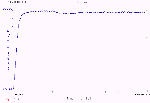
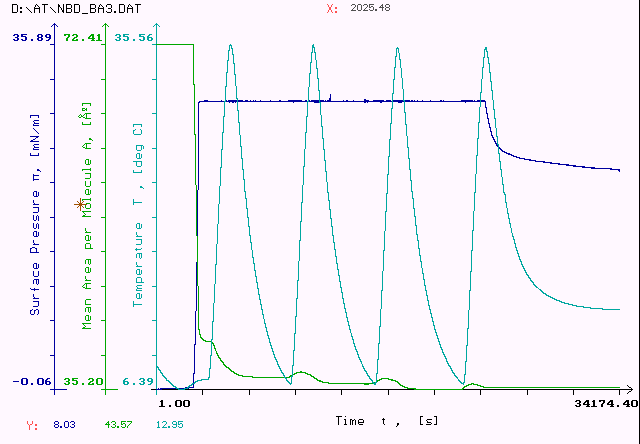
Constant temperature maintained at 38 OC.
Constant temperature maintained at 7 OC. After one hour from reaching the desired temperature the accuracy is ұ 0.1OC improving with time.
3.3. Surface pressure meterTwo basic designs exist of the Wilhelmy type surface pressure meters. One of them uses linear position sensor (usually linear variable differential transformer (LVDT)) for measuring the displacement of the Wilhelmy plate. The measuring element (the anchor in the case of LVDT) is attached to a spring so this becomes a force measuring unit. The advantages of this design are that it is not breakable, linearity is higher, the noise is lower, and the unit is more reliable. The drawbacks are the larger thermal drift if the environment temperature changes, fatigue in the spring which may require recalibration, and the change of the Wilhelmy plate position. The last drawback is solved with today's high sensitivity designs so that total displacement at full range can be made lower than 0.1 mm. The results presented below are with this type of design. The other design utilises an analogue microamperemeter on the indicator arm of which is attached the Wilhelmy plate. The arm is illuminated by a LED and throws shadow on a couple of photodiodes. The signal from the photodiodes is used to maintain the arm in constant position and the surface pressure is proportional to the current which flows in order to maintain that position. The advantages and disadvantages are discussed above. The major disadvantage is the fragility of the system. In fact the more accurate is the system the more fragile it is. Some of our customers had problems with this. All our competitors use this design. We also manufacture it and use it in our tensiometers. The performance of our system is shown in the specifications and is demonstrated below.
Noise in water ұ 0.005 mN/m. 10 meas/sec. 2 minutes. Averaging with K = 7.
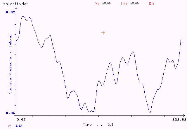
Long term drift. 4 hour experiment. One measurement every 5 seconds. No additional filtering. Drift is ұ 0.04 mN/m. With additional averaging the drift is ұ 0.02 mN/m.
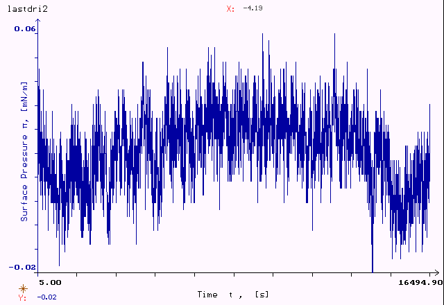
Drift in water for 6 hours. ұ 0.05 mN/m. No filtering.
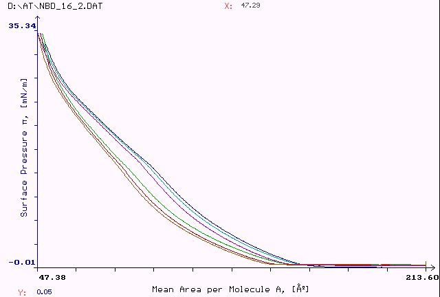
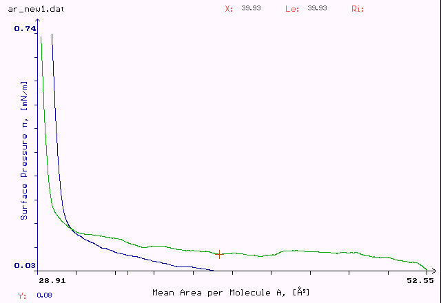
Reproducibility of surface pressure. 6 cycles of compression and decompression. From upper curve to lower curve: 1st compression, 2nd compression, 3rd compression, 1st decompression, 2nd decompression, 3rd decompression.
Reproducibility. A difference of 0.125 mN/m of the inflex point of Arachidic Acid
Reproducibility. 0.05 mN/m difference at low pressures. K = 5.
Reproducibility and noise in a real experiment. Additional averaging on data points was applied K = 7.
Liquid-gas coexistence region is clearly visible. It is seen also that compression velocity was high (observed also at liquid – solid coexistence).
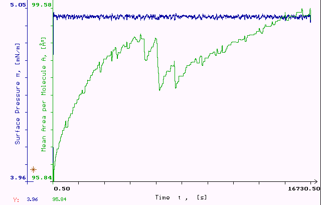
Constant surface pressure control at 5 mN/m. On the inset is zoomed surface pressure. Accuracy is better than ұ 0.03 mN/m.
Detailed comparison with other companies is not possible because no one from our competitors gives detailed information on the performance of their surface pressure meters. The parameters shown are the range – typically 0 – 100 mN/m, and a parameter, which they call accuracy – typically 0.004 mN/m. But this is not accuracy. This is resolution and it is obtained by dividing the range to the Analogue-to-Digital Converter resolution. NIMA and KSV use 16 bit resolution ADC. Compare this to ours 22 bit resolution ADC. Of this 16 bits, one is used for the sign, and remaining 15 bits give a resolution of approximately 1:32000. If you divide 100 / 32000 = 0.0031 you obtain the specified by them accuracy. But this is far from being true. First from theory of measurement it is known that you should have at least 4 times higher resolution to avoid discretization noise. That’s why in all our internal calculations we use 18 bit resolution. More importantly, the actual accuracy is limited by noise, long term drifts, repeatability, and nonlinearity. These parameters are specified for every analytical balance and the surface pressure meter is largely an analytical balance. But they are not specified by our competitors. It is true that in Langmuir film experiments absolute accuracy is limited by external factors like wetting angle, calibration accuracy, etc., to about 0.1 mN/m. But relative accuracy, i.e. a step or transition in an isotherm, is much higher. With our system we demonstrate measurement of liquid-gas coexistence region which is in our case (NBD – DPPE molecule) only 0.1 mN/m above the gas phase. From what we know about our competitors no one can measure this.
Demonstration of Isobars experiments.
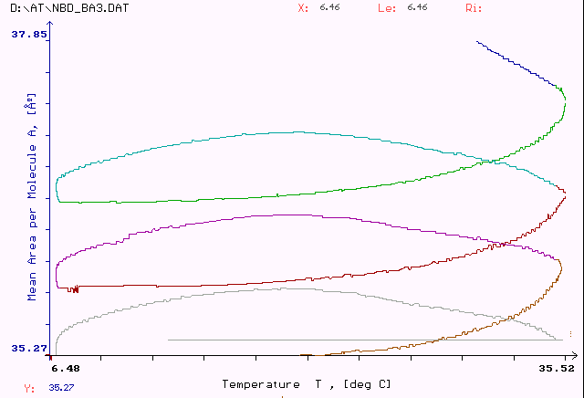
7 temperature cycles between 6.5 and 35.5 OC. The pressure was kept constant at 30 mN/m. On the lower curve is shown the change of area with temperature. This experiment would not be possible without the built-in compensation of water surface tension change with temperature.
Change of Mean Area per Molecule with temperature.
Relaxation of monolayer with temperature cycling can be observed. Its thermal
expansion coefficient can be calculated. Excellent reproducibility can be noticed.
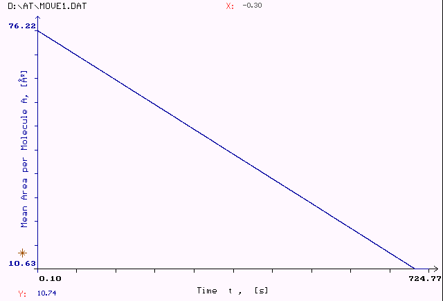
3.4. Mechanical modulesWe use the best possible design for both the barrier module and the lift module. This is the use of DC servomotors with analogue tachometer feed back loop for maintaining constant velocities. NIMA uses DC motors but the tachometer feed back is only an option, that is why their range is limited to 1:200. KSV uses DC motor only in their lift but with digital feedback – hence the dynamic range is limited to 1:100. For their barrier mechanism they use stepper motor in microstep operation. But when you specify a range of 1:40000 this means that the motor makes a step and then waits for several seconds. This inevitably generates surface waves and vibrations. NIMA and KSV use 12 bit Digital-to-Analogue Converters for motor control. Compare this to ours 14 bit DACs. We have 4 times better resolution which we can utilise by our mechanical design. In our case we use linear tachometer feed back as opposed to pulse-width modulation control. For small motors this is a far superior solution which increases motor life and decreases unevenness of motion. This in combination with the most precision slide rails and precision position sensors, attached to the end stage for true position readout, produces the best mechanical design. This is important not only for smooth, even, vibration free motion with large velocity range. This is important also in the surface pressure control in which the barrier acts as a feed back.
Accuracy of barrier motion. The area decrease versus
time is an absolute straight line with no deviations, indicating unevenness
or vibrations. The best way to test mechanics is to put your finger on a quickly
moving barrier or lift. You can feel the smooth motion and you can see the difference
with competitors.
4. ConclusionHere we have presented proof that the 500 series of Langmuir-Blodgett film deposition equipment from Advanced Technologies Ltd. is the most accurate and versatile system on the market. What is more, our system is at least 10 times more precise in all important parameters than the comparable system of our major competitor – NIMA Technology (U.K.). Compare:
KSV (Finland) system is better compared to NIMA. Very little official information is provided so what can be said at this moment is that our system is at least as precise as KSV in points 1 and 2 above. The rest 3 points are absolutely true again. And even the low cost models of KSV are approximately 2 times more expensive than a 500 system. Our software is more powerful and with more features. All possible data analysis functions are built-in. Export of the data file and setup parameters in ASCII format is available for data import in other software. The software has self-test and self-calibration features to make the system easy for work. Software protection of the system is combined with hardware protection in all modules. This adds to system reliability and to fault tolerance. We are currently establishing contacts with leading companies to distribute our products in the corresponding countries. This will give our products unparalleled support and our customers - piece of mind. Last but not least, our prices are at least 10 % lower than
the lowest prices on the market – the NIMA prices. And NIMA in most countries
operate without local distributor so it can not provide the customers’ support
that our distributors can. |