|
I. INTRODUCTION OF THE PATCH CLAMP METHOD The Patch Clamp/Whole Cell Amplifier (PCA) model 707 provides a method first introduced by E. Neher and B. Sakmann in 1976 for recording the currents in a small patch of membrane under voltage-clamp conditions. The model 707 is the last generation (designed in 2001) model combining several advantages made capable by the development of methodology and electronic industry. In recent years a number of technical advances have occurred, most notably the discovery of the “gigaseal” by E. Neher (1981). The advantage of the PCA mod 707 is that intracellular recordings can be made with the same type of recording setup as used for patch recording from the cell surface, as well as a cell-free membrane. The instrument can be used to perform electrochemical measurements. For an introduction to electrochemical methods you may refer to Kawagoe, Zimmerman and Wightman, J. Neuroscience Methods, 48 (1993) 225 – 240. Model 100 is a low cost alternative, capable of working only in Voltage Clamp (VC) mode and in either patch-clamp or whole cell mode selected when ordering the instrument. II. REFERENCES
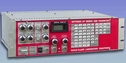
Patch Clamp Whole Cell Amplifier model PCA 707 The Patch Clamp Whole Cell Amplifier model PCA 707 from Advanced Technologies Ltd. represents the latest break through in the design of this type of instrumentation. It combines precise analogue electronics with onboard microprocessor controller which decreases noise, expands the instrument functionality and reliability, and allows bidirectional communication with a computer. The processor is powered only when a button is pressed thus it does not contribute to the noise.
Features: Operating Modes PCA Mod. 707 is fundamentally an instrument for measuring small electrical currents. It uses a current/voltage (I/V) converter circuit to convert the currents to an analog voltage which is then made available at the CURRENT monitor outputs for display and/or recording. At the same time that the pipette currents are being recorded the potential must be specified, and the various operating modes of the EPC-7 correspond mainly to different ways of controlling that potential. These operations include (see Fig. 2): A. Voltage-Clamp mode (V.C.) This is the basic patch-clamp mode. The pipette potential is derived from the signal applied to the STIM IN input with a variable offset added from the V-HOLD control. The sum of these two sources is what is displayed and monitored as the V.COMM signal. Before being applied to the pipette a further variable offset is added from the Vp-OFFSET control to allow the user to cancel electrode offsets. B. SEARCH mode and VOLTAGE CLAMP COMMAND (V. COMM) The SEARCH mode is essentially the same as the Voltage-Clamp mode, except that V.COMM also receives an input from the search integrator, which is an amplifier that provides negative feedback between the current monitor and pipette potential signals. It acts slowly to adjust the pipette potential to make the average pipette current zero. This mode of operation is most useful when one is first approaching a cell to make a seal, as the feedback will compensate for small electrode potential drifts that otherwise would drive the current monitor signal off-scale. The speed of the feedback is inversely proportional to the resistance between the pipette electrode and the bath, with a time constant of about 1 s at 10 MW . When a gigaohm seal is established the feedback becomes very slow. To avoid drifts in the pipette potential it is desirable to switch to the VC mode before starting a recording. C. Current Clamp modes (CC) The Current Clamp modes are similar in principle to the search mode, in that feedback is employed between the current monitor signal and the pipette potential. In the CC mode the feedback acts rapidly to keep the current at zero by varying Vp appropriately; in this way a high-impedance voltage follower is created, with the output voltage available at the POTENTIAL output. In the CC mode, to measure the resting potential (or spontaneous action potentials in whole-cell recording) the membrane potential will be shown on the display. In the CC+COMM mode, a command current can be injected while the pipette potential is measured. The command current is determined by the sum of voltages from the STIM. IN signal and the VHOLD control.
Technical Data NOISE
0 – 5 kHz .....................................................0.03 pA RMS MODES OF OPERATION VC (Voltage clamp); CC (Current clamp); CC+COM (Current clamp with command current); TEST, SEARCH CURRENT MONITOR SIGNAL Gain 0.5 – 1000 Internal Filter ……. 1/2/5/10/100 kHz 4-pole Low Pass Bessel TRANSIENT CANCELATION Compensates fast and slow transients with the control of fast and slow time constant and amplitude. Additional Whole Cell compensation circuitry which is calibrated. SERIES RESISTANCE COMPENSATION Controls for the time constant, % compensation, and lag. HEADSTAGE Current-measuring resistances.………0.5/20 GW , remotely switched LED indicator of the regime of work (Patch/whole cell) Input connector ……………..………..BNC Other connections…………………….Ground sense input, Pipette command output METER 3 1/2 – digit Liquid Crystal Display with 4 side LEDs to indicate the displayed units. Monitors: I – pipette current; IRMS – noise current; VP – Pipette potential; VCOM – membrane potential; VH –holding current or voltage. DIMENSIONS Headstage …………………… 55 x 90 x 20 mm (without the holder and the BNC) Headstage cable ………………1 m, highly flexible Controller …… …………….. 3U 19" rack chassis MODEL CELL Emulates whole cell or patch. 2 BNC connectors with no switches. Shielded. POWER REQUIREMENTS ……………100 - 230 V, 30 W. Please specify voltage on purchase. OPTIONS Model PCA 707/I is without some of the digital functions: the storage and retrieval of 6 sets of parameters, and the communication with the computer. We provide turn key solutions.
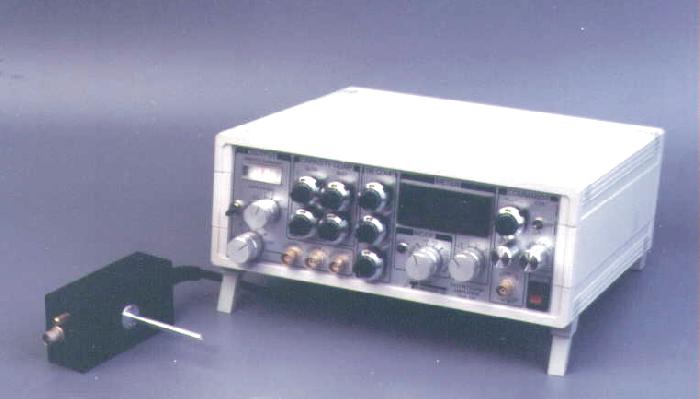
Patch-clamp amplifier model 100. Features
SpecificationsNOISE(Equivalent current input noise, measured with 4-pole Bessel filter, 50 Gohm range) 0 - 10 kHz.………………………………………………………….. 0.15 pA, RMS CURRENT MONITOR SIGNALGain 0.2 – 1000 two switch selected Switch x1 - 0.5 Gohm resistor Switch x 100 - 50 Gohm resistor Internal Filter ……. 0.3/ 1/ 3/ 10/ 30/ Off kHz 4-pole Bessel SERIES RESISTANCE COMPENSATIONControls for the % compensation, slow time constant and fast time constant. TRANSIENT CANCELLATION
Input connector ……………..………BNC Other connections…………………...Ground sense input and pipette command output. FUNCTION GENERATORTriangular or rectangular pulses with controls for the amplitude, polarity and frequency. METER3 1/2 – digit Light Emitting Diode Monitors: VH/IH –holding current or voltage; I – pipette current; IRMS – noise current; VM – membrane potential. POWER REQUIREMENTS85 – 240 V autoswitching, 30 W; EMC emission free. |